
How an Integrated Pneumatic Valve-Cylinder Assembly Works

Related Posts
How an Integrated Pneumatic Valve-Cylinder Assembly Works
February 24, 2026
How to Read Solenoid Valve Symbols and Identify Port Functions
February 24, 2026
Diagnosing Coil, Spool, and Spring Problems in Hydraulic Directional Valves
February 24, 2026
How Valve Opening Affects Flow Regulation
February 12, 2026
A pneumatic cylinder with a solenoid valve combines cylinder actuation and directional control in a compact assembly. By positioning the valve close to the cylinder, this design can reduce external tubing and simplify installation.
Depending on the configuration, the assembly may also include flow-control components to adjust cylinder speed. Selection should consider the operating pressure, cylinder bore and stroke, valve port arrangement, control voltage, and required motion.
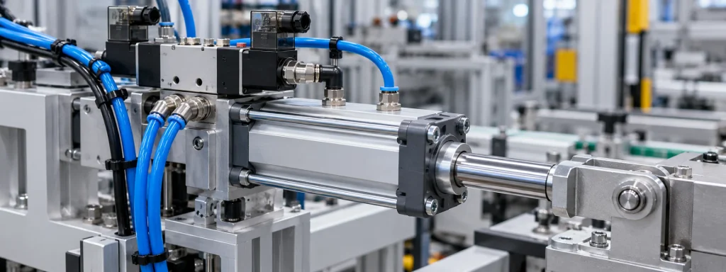
1. What Is an Integrated Pneumatic Valve-Cylinder Assembly?
An integrated pneumatic valve-cylinder assembly combines a pneumatic actuator with a directional control valve. Some configurations also include a one-way flow-control valve, mounting interface, fittings, and sealing components.
The integrated design can simplify pneumatic connections and reduce installation space. However, the actual configuration and performance depend on the manufacturer's design and the requirements of the application.
Typical components include:
- Pneumatic cylinder and piston assembly
- Solenoid directional valve
- Air supply and exhaust connections
- Flow-control components
- Seals, fittings, and mounting interfaces
2. How Does It Work?
When the solenoid receives an electrical command, the directional valve changes its flow path and directs compressed air to the specified cylinder chamber. Air from the opposite chamber is exhausted according to the valve configuration, allowing the piston and rod to move.
When the electrical signal is removed, the valve returns to its original position if it uses a spring-return design. A bistable valve may remain in its last switched position, depending on its construction.
The valve's switching behavior should be confirmed using the manufacturer's pneumatic symbol and technical documentation. A valve's ability to retain its position does not automatically mean the cylinder can safely hold a load after power or air pressure is lost.
3. Single-Acting and Double-Acting Configurations
Single-Acting Pneumatic Cylinder
A single-acting cylinder uses compressed air to produce movement in one direction and typically relies on a spring or external force for its return stroke. The actual arrangement depends on the cylinder design.
Double-Acting Pneumatic Cylinder
A double-acting cylinder uses compressed air alternately supplied to both sides of the piston to control extension and retraction. The directional valve must match the required port arrangement and operating sequence.
The appropriate configuration depends on the required force, stroke, cycle time, available air supply, and control strategy.
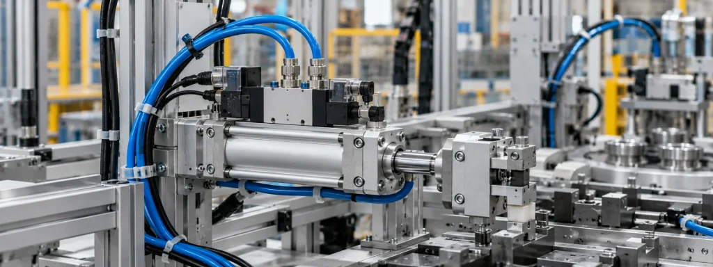
4. Flow Control and Cylinder Speed
Flow-control components can regulate the rate at which compressed air enters or leaves a cylinder chamber, affecting piston speed. A one-way flow-control valve may allow relatively free flow in one direction and restrict flow in the other.
The correct adjustment method depends on the circuit design and manufacturer's recommendations. Excessive restriction can affect response and operating performance, so speed settings should be verified under the intended load and pressure conditions.
5. Benefits and Design Considerations
Integrating a pneumatic cylinder and solenoid directional valve can reduce external tubing, simplify connections, and provide a compact installation.
Before choosing an integrated assembly, engineers should also consider maintenance access, compatibility with the control system, air supply requirements, mounting dimensions, and the availability of replacement components.
An integrated design is not automatically suitable for every application. The valve and cylinder must be specified as a compatible assembly.
6. How to Select a Pneumatic Cylinder with Solenoid Valve
Before selecting a configuration, confirm the following:
- Operating pressure: Verify the available compressed-air pressure and the assembly's rated operating range.
- Cylinder dimensions: Confirm bore size, stroke, installation space, and required output force.
- Valve configuration: Check the number of ports and positions, the pneumatic symbol, and the required switching sequence.
- Electrical requirements: Verify coil voltage, connector type, and compatibility with the control system.
- Flow and speed: Confirm the required cycle time and whether additional flow-control components are needed.
- Installation: Check mounting dimensions, air connections, and service access.
- Operating environment: Confirm temperature, contamination exposure, and any applicable environmental or safety requirements.
Always compare the intended application with the manufacturer's specifications before ordering or installing the assembly.

7. Frequently Asked Questions
What is a pneumatic cylinder with a solenoid valve?
It is an assembly that combines a pneumatic cylinder with an electrically actuated directional valve to control compressed-air flow and cylinder movement.
What is the difference between a single-acting and a double-acting cylinder?
A single-acting cylinder typically uses compressed air for one direction and a spring or external force for return. A double-acting cylinder uses compressed air to control movement in both directions.
Does a solenoid valve control cylinder speed?
The directional valve controls the flow path, while a suitable flow-control component can regulate airflow and adjust cylinder speed.
Will a cylinder stay in position if electrical power is lost?
Not necessarily. The behavior depends on the valve configuration, air supply, load, and any additional holding or safety mechanisms. Do not rely on the valve alone to secure a suspended or hazardous load.
What information is needed to select an integrated valve-cylinder assembly?
Provide the operating pressure, cylinder bore and stroke, required force and speed, valve configuration, coil voltage, mounting dimensions, and application conditions.
Need Help Selecting a Pneumatic Valve-Cylinder Assembly?
Share your application requirements, technical drawing, or existing component reference with XOIL to help determine a suitable configuration.
Share on Social:


- PREV: How to Read Solenoid Valve Symbols and Identify Port Functions
- NEXT: Null
Let’s Talk Together
Related Posts
How an Integrated Pneumatic Valve-Cylinder Assembly Works
February 24, 2026
How to Read Solenoid Valve Symbols and Identify Port Functions
February 24, 2026
Diagnosing Coil, Spool, and Spring Problems in Hydraulic Directional Valves
February 24, 2026
How Valve Opening Affects Flow Regulation
February 12, 2026


